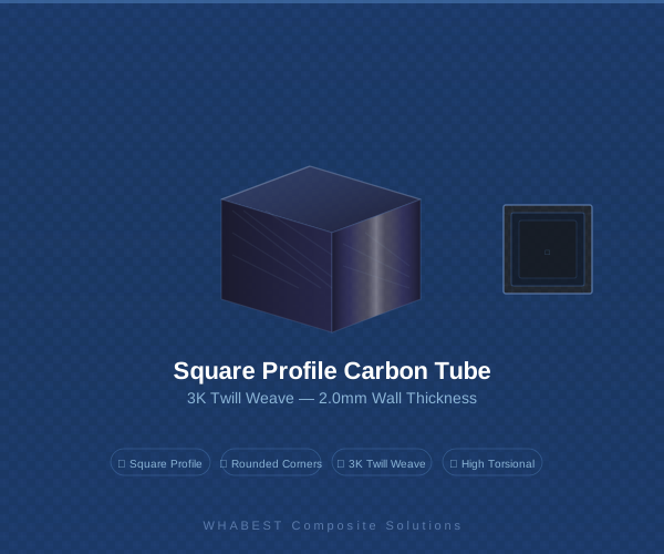
For fifteen years, WHABEST Composite Solutions has specialized in the precision manufacturing of high-modulus carbon fiber tubes. We have supplied pultruded and roll-wrapped profiles to the aerospace, automotive, and industrial automation sectors, where these tubes serve as the critical load-bearing skeleton in complex assemblies. Over the last decade, a significant engineering shift has occurred. Clients are no longer simply buying a tube to fit into a machined aluminum bracket. They are integrating it into a hybrid structure where the bracket is now a 3D-printed node of complex geometry.
This convergence of carbon fiber tube manufacturing with additive manufacturing represents a pragmatic engineering solution to two fundamental limits. Standard fused deposition modeling struggles to produce long, slender parts with high stiffness-to-weight ratios due to inherent layer anisotropy and limited build volumes. Traditional composite molding, while delivering exceptional specific strength, incurs prohibitive tooling costs for complex, low-volume fittings. Hybrid manufacturing bridges this gap by exploiting the strengths of each process: the continuous fiber backbone for global structural integrity and the 3D-printed interface for local geometric complexity.
Understanding Hybrid Manufacturing
Hybrid manufacturing in the context of carbon fiber tubes combines a thermoset composite tube with a thermoplastic 3D-printed component. The tube is manufactured via pultrusion or roll-wrapping. Pultrusion offers infinite length and a high volume fraction of unidirectional fibers, ideal for axial loads. Roll-wrapping, our primary specialty, allows for a tailored fiber architecture. A [0/±45/90]²S layup provides an excellent balance of axial stiffness, torsional rigidity, and bearing strength at the interface.
The role of the 3D-printed part is to act as the nodal connector. It absorbs the stress concentrations at the joint and transitions them into the uniform cross-section of the tube. This is a division of labor that leverages the physics of both manufacturing methods. The tube handles the global loads; the print handles the local complexity. The critical engineering challenge, and the focus of this strategy, is managing the transition zone between these two disparate material systems and their respective processing conditions.
Material Selection: Compatibility Between Thermoset Composite Tubes and 3D-Printed Thermoplastics
The compatibility between the tube material and the printed material is the most common root cause of hybrid assembly failure. The interface must manage three primary challenges: chemical adhesion, mechanical interlocking, and differential thermal expansion. Standard carbon fiber tubes utilize an epoxy thermoset matrix. This surface is inherently low-energy, making chemical adhesion to a thermoplastic like Nylon 12 or PETG non-trivial.
Surface preparation is non-negotiable. We recommend a three-step protocol: solvent degreasing, mechanical abrasion with 80-grit aluminum oxide, and atmospheric plasma treatment. In our joint testing lab, this sequence consistently yields lap-shear strengths exceeding 10 MPa on a 25 mm overlap. Without plasma treatment, the same joint configuration rarely exceeds 5 MPa. The adhesive itself is a critical variable. Two-part methacrylates such as 3M DP8010 are our top recommendation for high-stress applications. Unlike brittle epoxies, methacrylates retain toughness after cure, which is essential for absorbing cyclical thermal stress generated by the coefficient of thermal expansion mismatch between the carbon tube (near-zero CTE) and the printed thermoplastic (50 to 100 ppm per degree Celsius).
From an engineering material selection standpoint, we advise against using unreinforced PLA for any structural hybrid application. Its low glass transition temperature and susceptibility to creep under sustained load make it unsuitable for transferring meaningful loads into the carbon tube. If dynamic performance is required, Nylon 12 reinforced with chopped carbon fiber offers an excellent balance of stiffness, toughness, and thermal resistance. For high-temperature environments, PEKK or Ultem 9085 provides the required thermal stability.
Design Considerations: Tolerances, Bonding Methods, and Load Paths
The design of the hybrid joint dictates the ultimate performance of the component. This begins with dimensional tolerances. A precision roll-wrapped tube from WHABEST holds an outer diameter tolerance of plus or minus 0.05 millimeters. A well-calibrated FDM printer might hold a socket tolerance of plus or minus 0.20 millimeters. This mismatch means a theoretical press fit is rarely achievable without localized stress concentrations. We recommend designing for a controlled clearance of 0.10 to 0.30 millimeters to allow for a uniform adhesive bond line. This bond line thickness is critical for maximizing shear strength. Too thin, and the joint is brittle and prone to peel. Too thick, and the adhesive becomes the weak link due to its lower inherent shear modulus.
The joint geometry must place the adhesive in shear, not peel. A common failure mode we observe is a short, flush-bottomed socket. When thrust or moment loads are applied, the tube rocks out of the socket, placing the bond line in pure peel. The fundamental rule of adhesive joints applies here: the bond length to tube diameter ratio should be at least 2:1, and ideally 4:1, to fully develop the load transfer capacity of the tube into the printed node. A 20-millimeter diameter tube requires at least a 40-millimeter bond socket to be structurally efficient.
Internal features of the printed socket significantly enhance mechanical interlocking. Adding annular grooves or a hexagonal profile to the internal diameter provides a mechanical backup to the chemical bond. This redundancy is crucial for applications subject to high impact or thermal cycling. Furthermore, designers must consider print orientation relative to the load path. The layer lines of the FDM part should be oriented perpendicular to the primary load vector entering the joint to avoid delamination at the adhesive interface. Z-axis strength is the weakest link in FDM, and the joint design must mitigate this.
Key Applications: Drone Frames, Robotics, Medical Devices, and Tooling
The hybrid paradigm has found its strongest foothold in applications demanding a high stiffness-to-weight ratio combined with geometric complexity. Drone frames are the canonical example. A 16-millimeter by 14-millimeter UD carbon tube provides the cantilever arm stiffness, while a 3D-printed Nylon 12CF center hub integrates motor mounts, camera gimbal brackets, and landing gear nodes into a single, topology-optimized part. This reduces part count and assembly time dramatically compared to a fully machined aluminum chassis.
In industrial robotics, end-of-arm tooling benefits immensely. A standard carbon tube replaces a heavy aluminum support beam, reducing inertia and allowing for higher cycle speeds or the use of a smaller, less expensive robot model. The 3D-printed gripper jaws, vacuum manifolds, and sensor mounts are easily iterated for different parts without replacing the entire structural spine. This agility is invaluable in high-mix, low-volume production environments.
Medical device applications are emerging rapidly, particularly in prosthetics and exoskeletons. The structural frame uses standard carbon tubes for strength and fatigue resistance, while the cuffs and contact interfaces are 3D-printed from biocompatible materials based on 3D scans of the patient. This dramatically reduces the lead time and cost for custom assistive devices. Similarly, in manufacturing jigs and fixtures, a rigid carbon tube frame provides the global stiffness, while 3D-printed locators and grab bars provide the specific, often complex, contact geometry required to locate a part accurately.
Cost-Benefit Analysis: When Hybrid Manufacturing Makes Economic Sense
The economic threshold for hybrid manufacturing is a critical consideration for procurement managers. Compared to a fully composite assembly, which requires a complex and expensive female mold for the fitting, hybrid manufacturing eliminates tooling cost entirely. For volumes under one thousand units, this cost advantage is overwhelming. The tradeoff is a slight reduction in specific strength due to the inclusion of the adhesive layer and the thermoplastic node.
Compared to a fully 3D-printed structure, the hybrid approach offers superior material efficiency and build speed. Long, structural components are expensive to print due to high material usage and long build times. Replacing a 400-millimeter long arm with a carbon tube that costs a fraction of the printed material is a clear economic win, independent of the strength advantages. The hybrid approach also allows scaling to very long geometries, beyond the build volume of standard industrial 3D printers.
The hidden cost in hybrid manufacturing is assembly labor. Surface preparation, adhesive dispensing, fixturing, and cure time require skilled technicians and process control. Automation of this step through robotic dispensing and CNC assembly fixtures is the key to making hybrid viable for higher volumes. When evaluating hybrid, the design engineer must weigh the material savings and performance gains against the labor cost of assembly. For very high volumes, injection-molded overmolding remains the faster, more consistent process, but requires significant tooling investment.
Case Example: High-Performance Hybrid Drone Arm
To illustrate these design principles, consider a case study from our WHABEST engineering archives. A client developing a heavy-lift drone required a 350-millimeter arm capable of supporting a 4-kilogram thrust motor. The tube selected was a WHABEST RT-200 roll-wrapped profile with a [0/±45/90] symmetric layup, providing an axial compressive modulus of 180 GPa.
The client initially designed a 3D-printed Nylon 12CF motor mount with a simple cylindrical socket. During initial static load testing, the joint failed at the interface at loads well below the target. The failure mode was pure adhesive peel, exacerbated by a bond length of only 15 millimeters. The resolution involved a collaborative redesign of the printed mount. We specified three key features: a 30-millimeter bond length, a slight taper at the socket entry to relieve peel stress concentrations, and internal annular grooves to provide mechanical interlocking. The bonding protocol was standardized to include grit blasting and a methacrylate structural adhesive.
After these modifications, the hybrid assembly passed a 20-kilogram static proof load test without bond failure or measurable creep. The final hybrid arm weighed 38 grams, compared to 58 grams for a fully printed arm and 48 grams for an equivalent aluminum arm. The tooling cost was effectively zero, and the total per-unit cost was 40 percent lower than the fully composite alternative for the initial production run of 500 units.
Future Trends: Continuous Fiber Printing, Embedded Sensors, and Automated Production
The future of hybrid manufacturing is moving toward tighter integration. We are developing tube profiles specifically optimized for additive overprinting. By using a co-cured thermoplastic surfacing film on the outer diameter of the tube, the chemical bond strength between the tube and the subsequent 3D print can approach cohesive strength in the plastic. This blurs the line between the structure and the connector.
Simultaneously, the additive sector is maturing. Continuous fiber printing technologies from companies like Markforged and Anisoprint now allow the printed node itself to have a continuous carbon fiber backbone. The ultimate hybrid component will consist of a pultruded core for axial efficiency, a continuous fiber printed node for joint strength, and a short fiber printed overmold for complex features and surface finish. This multi-scale composite approach represents the logical endgame of the hybrid concept.
Embedded sensorization is another frontier. The 3D-printed component can easily integrate channels for fiber optic strain sensors or cavities for wireless telemetry modules. Future automated hybrid production lines will combine robotic tube placement, in-line surface plasma treatment, and 3D printing heads that build the node directly onto the tube. This eliminates the tolerancing issue of the socket entirely and removes the labor bottleneck of manual assembly.
Conclusion: Practical Recommendations for Engineers Exploring Hybrid Approaches
Hybrid manufacturing combining carbon fiber tubes and 3D printing is not a compromise; it is an optimization strategy. For the practicing engineer, our recommendations are clear. Source the highest quality, most dimensionally consistent tube available. The tolerances of the tube govern the entire joint design. Invest heavily in the surface preparation protocol; it is the most common point of failure. Design the joint geometry to load the adhesive in shear and provide a mechanical interlock as a safety backup. Finally, test the assembly exhaustively in its intended environmental conditions to validate the CTE compatibility and creep resistance of the adhesive system.
Do not default to 100 percent additive manufacturing for long, slender structural components. Do not default to 100 percent composite molding for complex, low-volume connectors. Look at the load path. Where it is axial and global, use a tube. Where it is complex and nodal, use a print. At WHABEST Composite Solutions, we are committed to providing the precision carbon fiber tube stock that makes these ambitious hybrid designs possible. We invite engineers to contact our technical team to discuss the specific layup, tolerance, and surface finish requirements for their next-generation hybrid assembly. The convergence of these technologies is just beginning, and the boundaries between structure and connector will continue to dissolve.
Have a project in mind? Contact our engineering team for a technical consultation and customized solution.